At LAPAN (Indonesian Aviation- and Aerospace-Agency) in Rancabungur (Satellite Technology Center) the EGIS Rotor is going to be used for positioning of three antennas at the same time: a VHF-, a UHF- and a S-band antenna. The installation will be of use for communication with earthnear, circulating satellites as for example "Tiungsat 1" (uplink VHF 144 MHz and downlink UHF 430 MHz) and "Amsat AO40" (uplink UHF 430 MHz and downlink S-band 2400 MHz). Details of this installation: click here.

Photo 160
Altogether this rotor (360° AZ/90° EL) carries:
  • 140 cm Ø mesh-dish for 13 + 23 cm
  • 90 cm Ø offset for 3 cm/10 GHz
  • 30 cm Ø primfocus for 1.5 cm/24 GHz
  • 21 element-yagi for 70 cm
  • mounting-devices plus frameworks (vertical carrier!)
  • all transverters and power-amplifiers in casted alu-housings, simultaneous AZ/EL movements (55 kg), antennas/rotor are located at the roof of an 8-story building, distance from the shack approx. 40 m

Photo 6
A very interesting rotor application can be found at RBB "Radio-Berlin-Brandenburg" (former "SenderFreiesBerlin"): ENG vehicles in the city and in the region are controlling EGIS rotors via notebook computers and cellular radio connections. These rotors are mounted on a high building at the broadcast controll center. A directional microwave antenna can be adjusted automatically via notebook – GSM – modem – control unit – rotor right onto the ENG vehicle. On duty are 4 rotors – one for each quarter of the compass rose respectively.

Photo 166
Photo 167
Equipment Gesellschaft für Internationale Elektronik Systeme
Select Language: German - English
EGIS-Logo Back to the previous page | Back to the homepage Photo 1

Antennen-Rotor


a d d i t i o n a l   p a g e   w i t h   f u r t h e r   i m a g e s
Photo 1


Photo 207 The CubeSatellite "Compass 1", which
has been developed, built and taken
into space by 'Aachen University of Applied
Science' will also be monitored and controlled
from there via an uplink station. As this satellite
belongs to the LEOS, the antennas must be
continuously tracked to communicate with the
satellite. This task was taken over by an EGIS
Two-axial-tracker CL (Az = 360° & El = 90°)
– successfully.
Deutschland Radio "ProfiTracker"
in duty at
"Deutschland
Radio" Berlin
Photo 8 two 1.8 m offset antennas
of ANDREW company:
one with an EGIS rotor,
one with a fixed alignment
Photo 22 top on climb-in latt, ce-steel-tower,
rotor with directional radio antenna
(diam. 1 m) in "tower front mounting";
for high frequencies with flexible
waveguide
Photo 8 Rotor with 90° head for astronomic
application. Azimuth rotating axis is
mounted parallel to the earth's axis.
(Radio-astronomic Department
"German Museum", Munich – Photo
Reg. Nr. R3665/17).
Photo 208 In the Institute for Flight Guidance at
the German Aerospace Center (DLR)
in Brunswick (Braunschweig) the EGIS-
Tracker supports VHF point-to-point Yagi
antennas and is used for the tracking of
flight-objects to transmit measured data.
Photo 27 EGIS Bi-Axial-Rotor
with a Techni-Sat
parabol-antenna
Photo 138 Optimal use of the EGIS rotor: in the center is a parabolic antenna,
on the right an 10cm and an 23 cm antenna and on the left a video
camera. In all those different operations the special capabilities of
the EGIS rotor with 360 degrees all around sight and 90 degrees
Elevantions-Hub (horizon zo zenit) gets used.
Photo 141 EGIS rotors in
use at Bavaria-
TV, Munich/
Germany
Photo 99 Photo 7 1.8 m Ø fiber-
reinforced-resin
parabolic antenna
with mechanical
interface and rotor
on mast top
HAM application
Photo 2 Photo 28 rotor, standing here since about a
decade in task for the "DLR Deutsche
Forschungs-Anstalt für Luft- und
Raumfahrt" (GSOC German Space
Operations Center) in Oberpfaffenhofen/
Germany
Photo 9 90°/360° rotor
with 1.8 m solid
dish on a grated
mast
Photo 167 A very interesting rotor application can be found at RBB "Radio-Berlin-Brandenburg"
(former "SenderFreiesBerlin"): ENG vehicles in the city and in the region are controlling
EGIS rotors via notebook computers and cellular radio connections. These rotors are
mounted on a high building at the broadcast controll center. A directional microwave
antenna can be adjusted automatically via notebook – GSM – modem – control unit –
rotor right onto the ENG vehicle. On duty are 4 rotors – one for each quarter of the
compass rose respectively.
Photo 24 rotor on lattice-steel-
tower with parabolic
antenna (diam. 3 m/
10 ft) with counter-weight
operational in winter
Photo 4 To reduce wind load plane and
advance survival chances of the
entire antenna system in stormy
weather you may steer the rotor
head in a horizontal position to
prevent any damage (here shown
on an skyscraper with an 1.8 m
dish).
Photo 146 Upon an offshore oilrig the rotor (with
AZ = 360°) carries 4 stocked up yagi
antennas. Telemetry data and remote
control signals are transmitted from
and to service ships.
Place: Gulf of Oman.
Photo 162 Heated prime-focus-antenna
(2.1 m Ø kathrein) at the
"Hessischer Rundfunk" in
Frankfurt/Germany. Tracked
by the EGIS rotor.
Photo 6 Alltogether this rotor (360° AZ/90° EL) carries:
  • 140 cm Ø mesh-dish for 13 + 23 cm
  • 90 cm Ø offset for 3 cm/10 GHz
  • 30 cm Ø primfocus for 1.5 cm/24 GHz
  • 21 element-yagi for 70 cm
  • mounting-devices plus frameworks (vertical carrier!)
  • all transverters and power-amplifiers in casted alu-housings, simultaneous AZ/EL
    movements (55 kg), antennas/rotor are located at the roof of an 8-story building,
    distance from the shack approx. 40 m
Photo 135 mobile exploratory and
measure lab in desert
use with data-uplink via
satellite
Photo 130 The company ScientificAtlanta
uses EGIS products, too. Two
EGIS rotors in duty.
Photo 182 EGIS rotors in 'Museum for
Natural History' New York/USA,
department 'Outer Space and
Astro Universum' in 'Hall of
Planet Earth'.
Photo 3 shown here is a rotor (360° AZ/
90° EL) supporting a 90 cm
parabolic bowl antenna in the
center with different Yagi
antennas
Photo 186 
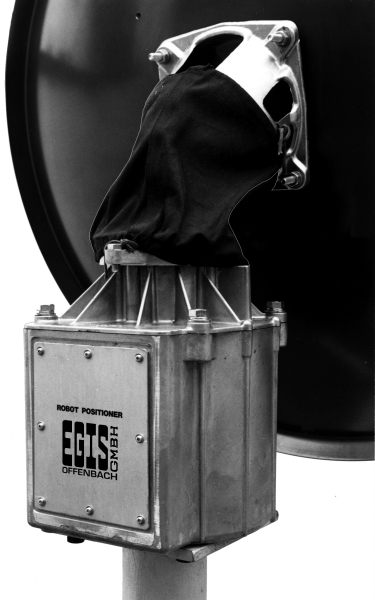
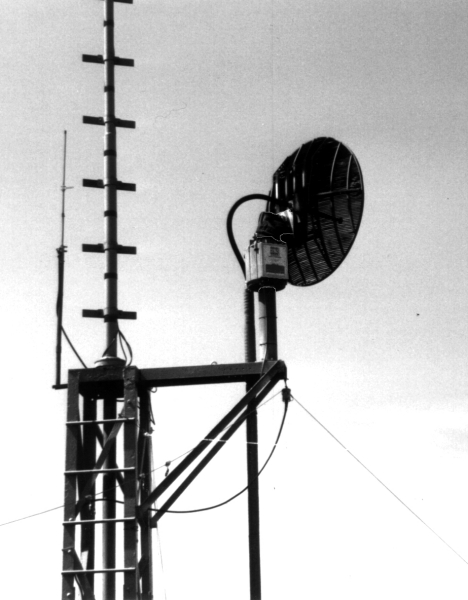
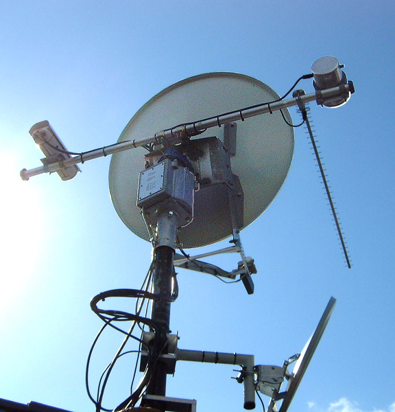
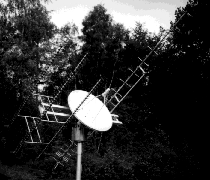
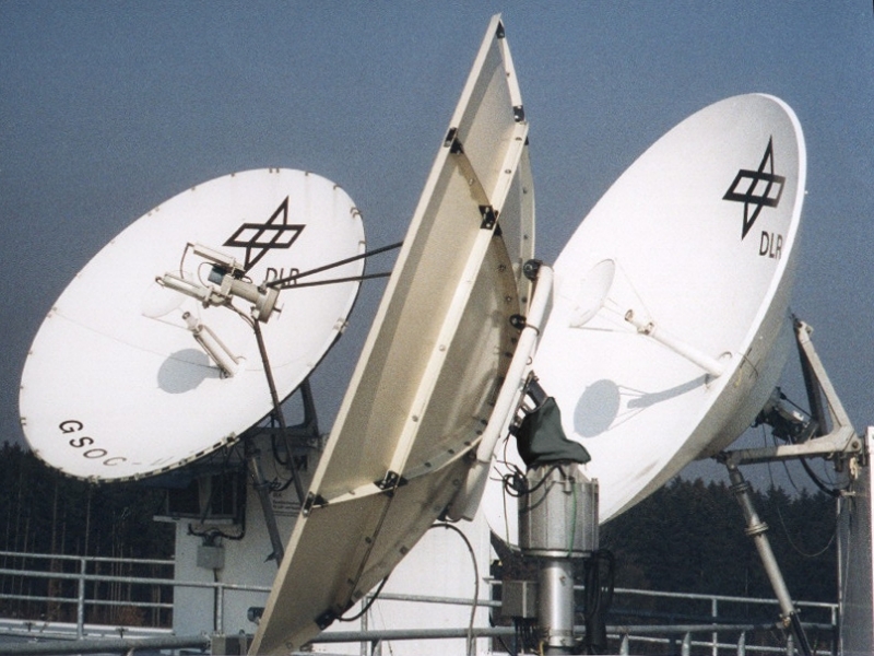
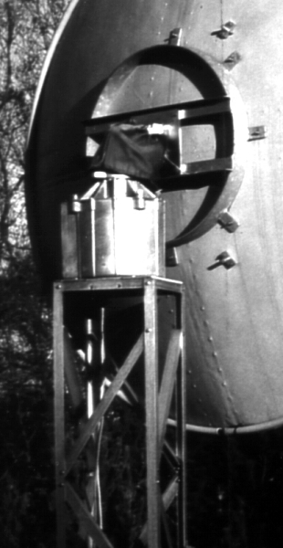
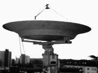
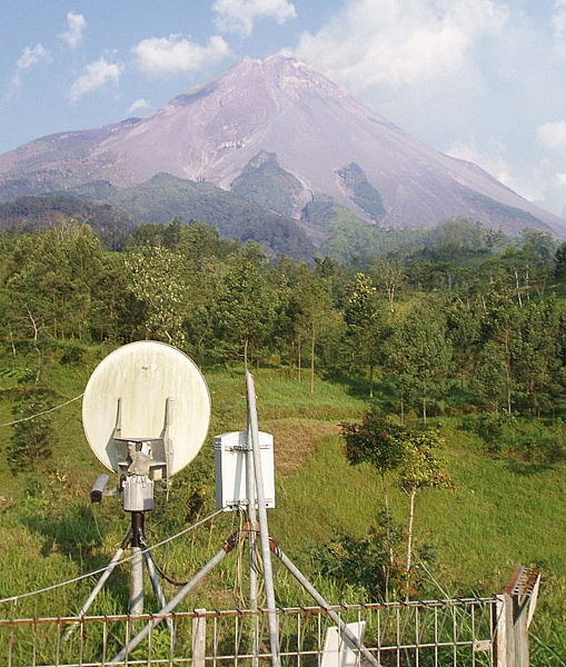
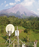
At the vulcano 'Merapi' in Indonesia the EGIS two-axis-
anntenna-rotor is used for communication between the
aloft sensor station being positioned in dangerous
surroundings and the measuring laboratory down in the
valley. The device has been developed, built and also
installed by the Institute of Geophysics at Hamburg
University. Nowadays it is run by the 'Merapi Vulcano
Observatory' in Yogukarta/Indonesia. The same
device is used at Mount Pinatubu/Indonesia.
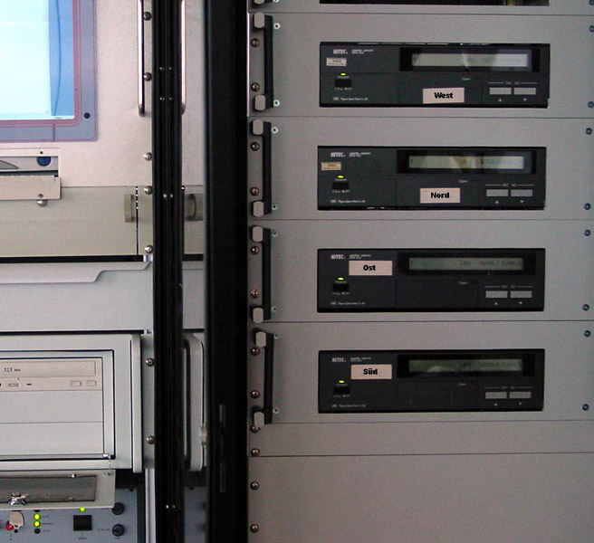
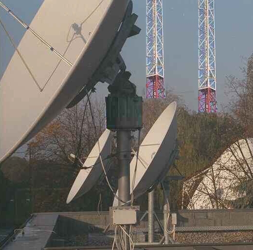
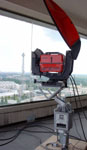
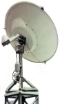
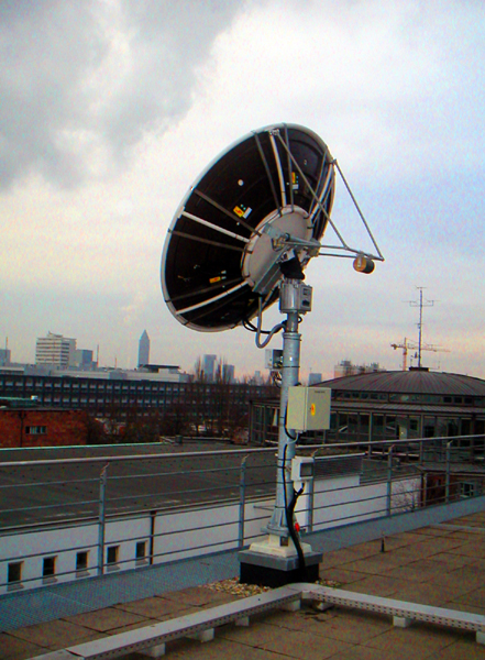
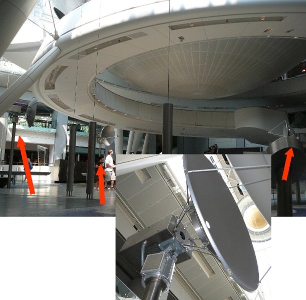
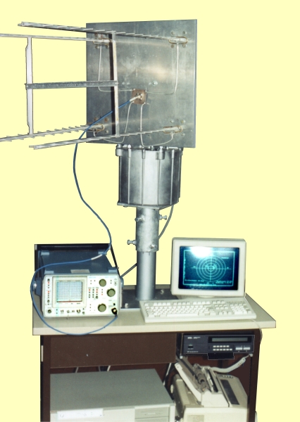
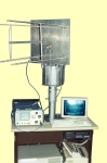
Photo 67 automated antenna
test site with computer
control, plotter, frequency
analyzer and EGIS rotor
Photo 151 rotor in use for report
at an SNG uplink station
(VSAT) in Afghannistan
Photo 140 different rotor systems
in use at the "Erstes
Deutsches Fernsehen"
(ARD) in Germany
Photo 173 here the EGIS rotor
with special feed/LNB
in a special task at
SES-Astra (Betzdorf/
Luxembourg)
Photo 148 EGIS rotors position a
directional microwave
radio antenna at RTL in
Luxembourg (Dep.
Broadcast Services)
Photo 161 At LAPAN (Indonesian Aviation- and Aerospace-Agency)
in Rancabungur (Satellite Technology Center) the EGIS
Rotor is going to be used for positioning of three antennas
at the same time: a VHF-, a UHF- and a S-band antenna.
The installation will be of use for communication with
earthnear, circulating satellites as for example "Tiungsat 1"
(uplink VHF 144 MHz and downlink UHF 430 MHz) and
"Amsat AO40" (uplink UHF 430 MHz and downlink S-band
2400 MHz). Details of this installation: click here.


Back to the previous page | Back to the homepage
Top